
Why Choose Bevel Gears for Industrial Applications?
Why Choose Bevel Gears for Industrial Applications?
Bevel Gears help industrial machines transfer power between intersecting shafts, often at right angles. This geometry supports compact layouts in conveyors, mixers, pumps, and material-handling equipment. In practical installations, engineers value their ability to redirect torque without adding unnecessary drive components. A well-selected bevel gear set can run smoothly, reduce space requirements, and maintain dependable motion under demanding loads. That matters on a factory floor, where every vibration, temperature change, and maintenance delay affects productivity.
Performance depends on more than gear shape. Tooth design, material quality, lubrication, alignment, and housing stiffness all influence service life. Experienced engineers normally review torque, speed, shock loads, operating temperature, and duty cycles before choosing a configuration. Spiral bevel gears may provide quieter operation and higher contact ratios, while straight bevel gears can offer simpler manufacturing and maintenance. The best choice is rarely universal. It depends.
Real-world results also depend on installation discipline. Even a precisely manufactured gear can wear quickly when shafts are misaligned or lubrication is neglected. Regular inspections can reveal pitting, unusual noise, rising temperatures, or backlash before serious damage develops. Bevel Gears are not a perfect solution for every transmission; hypoid, helical, or chain systems may suit certain layouts better. A reliable decision combines manufacturer data, field experience, and measurable operating requirements. Careful evaluation may take longer, but it often prevents costly redesigns and unexpected downtime.
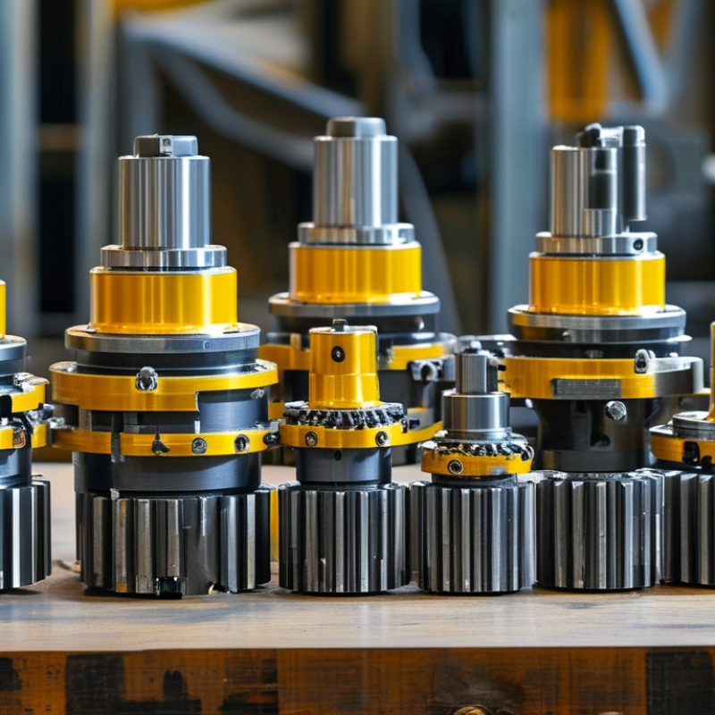
Table of Contents [Hide]
What Are Bevel Gears and How Do They Work?
Bevel gears are toothed wheels shaped like truncated cones. They transfer rotation between intersecting shafts, often at 90 degrees. The principle is simple. As one gear turns, its teeth push against the mating gear’s teeth. This changes the direction of power while maintaining controlled motion. The gear ratio depends on tooth counts. A smaller pinion driving a larger gear reduces speed and increases torque.
Straight bevel gears suit moderate speeds and simpler machinery. Spiral bevel gears use angled teeth, creating smoother engagement and lower noise. In industrial gearboxes, engineers select the tooth form, pressure angle, ratio, and shaft arrangement together. A properly designed housing keeps the shafts aligned. Lubrication then reduces heat, friction, and tooth wear. Small alignment errors matter.
In practical installations, bevel gears appear in conveyors, machine tools, pumps, and material-handling equipment. They are useful when a compact drive must redirect power without adding a separate chain stage. Their main advantages include strong torque transfer, flexible layout, and dependable operation under changing loads. However, bevel gears are not automatically the best choice. Poor lubrication, excessive backlash, or inaccurate mounting can cause vibration and premature failure. A calculation may look convincing on paper, yet field conditions often reveal overlooked shock loads. I would inspect tooth contact patterns during commissioning, not rely only on catalog ratings. That extra check can expose problems early, though it cannot replace correct engineering analysis.
Why Choose Bevel Gears for Industrial Applications?
| Data Dimension | Technical Information | Industrial Relevance |
|---|---|---|
| Definition | A bevel gear is a toothed gear with teeth arranged on a conical surface. It transmits rotary motion and torque between intersecting shafts. | It is suitable for machinery that requires a change in the direction of power transmission. |
| Typical Shaft Arrangement | Most bevel-gear drives connect shafts at a 90-degree angle, although other intersecting shaft angles are possible. | The arrangement allows designers to redirect power where a parallel-shaft gearbox would not fit. |
| Operating Principle | When the driving bevel gear rotates, its teeth mesh with the mating gear and transfer force along the conical tooth surfaces. | Continuous tooth engagement provides controlled speed and torque transfer when the gears are correctly aligned and lubricated. |
| Speed and Torque Relationship | For an ideal gear pair, output speed is approximately proportional to the ratio of input gear teeth to output gear teeth. Torque changes in the opposite direction, excluding losses. | A larger driven gear can reduce output speed while increasing available output torque. |
| Common Gear Ratio Range | Single-stage bevel gear sets are commonly designed for moderate ratios, often approximately 1:1 to 5:1. The practical range depends on tooth geometry, load, speed, and noise requirements. | Multiple stages may be used when a larger overall reduction is required. |
| Straight Bevel Gears | The teeth are straight and extend radially toward the apex of the cone. | They can be relatively simple to manufacture and are often used at low or moderate speeds, but they generally produce more noise and vibration than spiral designs. |
| Spiral Bevel Gears | The teeth are curved and engage progressively rather than all at once. | They normally provide smoother, quieter operation and greater load-carrying capability, making them useful for higher-speed industrial drives. |
| Zerol Bevel Gears | These gears have curved teeth with a spiral angle close to zero. | They combine some characteristics of straight and spiral bevel gears and can be selected when moderate smoothness and controlled axial loading are required. |
| Hypoid Gears | Hypoid gears are offset spiral bevel gears whose shafts do not intersect. Their tooth surfaces involve significant sliding as well as rolling contact. | They can provide compact right-angle drives and increased gear-pair contact, but they require suitable lubrication and careful thermal management. |
| Directional Flexibility | Bevel gears can redirect rotary power through a selected shaft angle, commonly 90 degrees. | This helps simplify layouts in conveyors, pumps, mixers, machine tools, material-handling equipment, and processing machinery. |
| Mechanical Efficiency | Well-designed and properly lubricated bevel gear drives can achieve high mechanical efficiency. Exact efficiency depends on tooth form, ratio, speed, load, lubrication, alignment, and bearing losses. | High efficiency can reduce energy losses and operating costs compared with less suitable transmission arrangements. |
| Load Capacity | Load capacity is determined by tooth bending strength, surface durability, material, heat treatment, face width, pitch, speed, and lubrication. | Industrial systems can be sized for heavy torque transmission when the gear set, shafts, bearings, and housing are engineered as one system. |
| Axial and Radial Forces | Bevel gear tooth geometry generates radial forces and, especially in spiral designs, axial thrust forces. | Shafts and bearings must be selected to withstand the combined forces without excessive deflection or premature wear. |
| Noise and Vibration | Straight-tooth bevel gears generally have more abrupt tooth engagement. Spiral-tooth designs engage gradually and can reduce noise and vibration. | Lower vibration supports improved operator comfort, equipment reliability, and product quality in precision machinery. |
| Typical Materials | Common materials include alloy steels, carbon steels, stainless steels, cast irons, bronze, and engineered polymers. Material selection depends on load, speed, temperature, corrosion exposure, and noise requirements. | The correct material can improve wear resistance, fatigue life, corrosion resistance, or weight efficiency. |
| Heat Treatment | Industrial steel bevel gears may use carburizing, nitriding, induction hardening, or through-hardening to improve surface durability and fatigue resistance. | Heat treatment can extend service life, but it must be controlled to limit distortion and preserve tooth accuracy. |
| Lubrication | Gear oil or another application-appropriate lubricant reduces friction, removes heat, and protects tooth surfaces from wear and scuffing. | Correct lubricant viscosity, cleanliness, level, and replacement interval are essential for dependable operation. |
| Alignment Requirement | Accurate shaft positioning, bearing support, backlash, tooth contact, and housing rigidity are critical to proper bevel gear operation. | Misalignment can cause uneven contact, noise, heat generation, tooth damage, and shortened service life. |
| Space Efficiency | A bevel gear set can transmit power through a right-angle arrangement without requiring two separate transmission systems. | This can reduce the installation footprint and simplify compact machine layouts. |
| Maintenance Needs | Routine maintenance generally includes checking lubricant condition and level, inspecting seals and bearings, monitoring temperature and vibration, and verifying tooth contact when necessary. | Condition monitoring helps identify misalignment, overload, lubrication problems, and progressive wear before a major failure occurs. |
| Main Advantages | Right-angle power transmission, compact arrangement, controllable speed reduction, high torque capability, and availability of smooth spiral-tooth designs. | These characteristics make bevel gears a practical choice for many industrial power-transmission systems. |
| Main Limitations | They can be more sensitive to alignment and manufacturing accuracy than simple spur gears. Spiral and hypoid designs may also create axial loads, sliding losses, and greater lubrication demands. | They should be selected only after evaluating load, speed, temperature, noise, maintenance access, and installation accuracy. |
| Selection Criteria | Important inputs include transmitted power, input and output speed, torque, shaft angle, duty cycle, shock loading, service factor, operating temperature, noise limits, available space, and expected service life. | A complete application analysis helps ensure that the gear set and supporting components are correctly rated. |
Technical values and performance depend on the specific gear geometry, materials, manufacturing accuracy, operating conditions, and installation quality. Final selection should be verified using recognized gear-design standards and application-specific calculations.
